|
When your part is complete save it as you would normally. So
you do not loose any of your work.
Now go to the File menu and
click SAVE AS
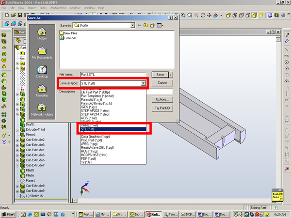
The Save As dialogue box below will pop up. Scroll through the file types
until you come to STL(*.stl) as seen below. Click that file type name
your part.
Advanced Exporting
For more advanced functions you can click the Options
button to the left of the pick box. The STL properties box below will pop up. This allows you to control the resolution and units of the STL file that is output from SolidWorks. Output As
You will always output the file type as Binary. It creates a smaller file size.
Units
Notice on the top there is a Unit: box. Select the units you want to work with in SRP Player. This should keep you from having to scale the part once it is brought into SRP Player. Resolution
Notice the Resolution items. Let me take a moment and explain resolution as it applies here. When SolidWorks exports a file to STL, it basically creates a polygon mesh of the current geometry. This polygon mesh is a representation of the current geometry. These settings give you the ability to tell SolidWorks how accurate this mesh needs to be. Keep in mind that the higher the accuracy of the mesh creates a larger file size and a more dense mesh. It is important to create the mesh so that it has the maximum tolerance you can live with for the part. This helps with the STL file size and also helps SRP Player to be able to work with this file in a timely manner. Dont let this overwhelm you I use basically only one setting every time. It is only when I have a very large part that seems to take a while for SRP Player to generate code that I come in here and change settings. Angle Setting
There are two settings for the resolution. There is the Angle setting. This determines how many faceted faces that the mesh breaks down a curved surface into. The higher the angle number the fewer the faces the lower the resolution. The lower the number then more faces will be created and the higher the resolution. For example if you were making a part that was very mechanical and it did not have curved surfaces, you would not need to worry much about this setting. However if your part had a lot of curved surfaces then you would want this setting to be very low to create a greater number of faces to the curved surfaces on the part.
Deviation Setting
The second setting for resolution is the Deviation setting. What this allows you to do is to determine how fine the mesh will be in regards to a tolerance. When SolidWorks breaks the geometry down into a mesh, it basically takes the geometry and overwrites it. This command allows you to tell SolidWorks what the maximum allowable tolerance is for mesh with respect to the model geometry. The lower the tolerance the higher the resolution and the larger the file size.
Standard Settings
SolidWorks has some standard settings already created for you. They are the Coarse setting and the Fine setting. For prototyping I hardly ever use the coarse setting. I do use the fine setting when I have a large part. The problem with the coarse is the angle of the faceted faces. It sets the setting to 30 degrees this makes a very choppy part. The deviation tolerance allows the mesh to be off only six thousandths this is not bad but not accurate enough for small work. The Fine setting sets the angle for faces to 10 degrees. This is good for large projects but not very good for small projects. The deviation that it allows at this setting is two thousandths. This is not bad for small projects. Recommended Settings
We normally use custom settings. I have found that 2.5 degrees is a good setting for the angle and .0005 is a good setting for the deviation. If the file is to large or SRP Player and has a hard time dealing with a part. I will use Fine to make SRP Player calculate the tool paths faster. Also use this setting if you get a Out of Memory error. Conclusion
The best thing to do would be to make some files on both ends of the settings so you can see the differences. 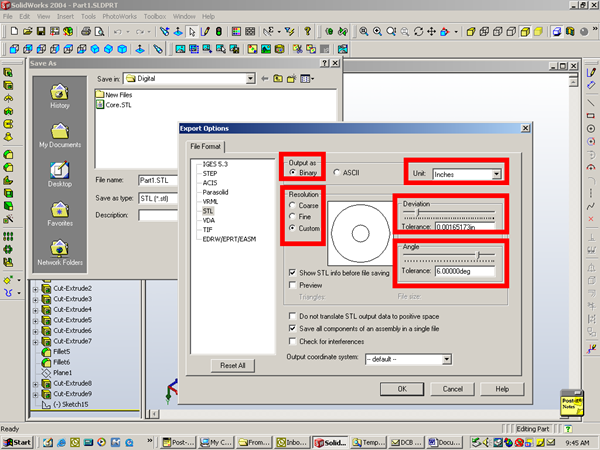
|